RATIONALE. Fish passages
Connectivity of freshwater ecosystems should take account of the movement of freshwater species and also the hydrological flow of nutrients (Ormerod et al., 2011). Therefore, the best way of ensuring freshwater ecosystem connectivity is through viaducts, multiuse underpasses or even adapted culverts. Measures to ensure fish movements in small culverts are often not considered, with the focus only on channelling the water (Hotchkiss & Frei, 2007; Closs et al., 2016). Suitable adaptation of such small drainage structures is crucial to restore not only water flow but also to maintain or restore fish connectivity. The recommendations included in this section are based on standards provided in Baudoin et al (2014) and SETRA (2013).
General description and targets
The ecologically best way to provide continuity for river and streams where crossing an infrastructure are viaducts or large adapted culverts (see Section 5.5.6 – Adapted viaducts (Landscape underpasses) and Section 5.5.10 – Adapted culverts) which allow to maintain both water course and riparian habitats on both sides. Smaller pipe or box structures than only transport water often pose a movement barrier to fish. This section focusses on how to adapt such small structures to enable fish to cross. However, adaptation of existing culverts in some situations could be so problematic that replacement with a new specially-designed structure is necessary.
Fish must be able to move freely both upstream and downstream. This is important not only for fish but other species, such as the larvae of freshwater mussels, transported in the gills of fish. Barriers created by infrastructure mainly restrict upstream movements, which are particularly important when fish migrate to their spawning grounds. This section provides general guidelines to facilitate fish crossing, but specialist consultation will be required as each species has many specific requirements and every site has its own specific conditions.
Location
Fish passages should be constructed where infrastructure crosses fish habitats such as rivers, streams and lakes. The design of the passage is determined by the requirements of the target species and constraints of the site, such as features of the structures already built. Important characteristics to be considered are:
- length
- slope
- width or diameter
- bottom substrate.
The design of a passage for aquatic species is different to that for terrestrial species and must take into account water flow fluctuation, velocity and volume, type of watercourse (natural stream, ditch or canal), continuity to be achieved and requirements of target species which will use the passage.
A ditch which has only a hydraulic function and does not allow fish to swim does not provide the same opportunities as a watercourse which is also an aquatic habitat. Where fish populations exist, additional assessment work is required and regulatory obligations need to be fulfilled in the design of the crossing structure.
Design
- An excessive drop at the entrance or exit of the passage must be avoided.
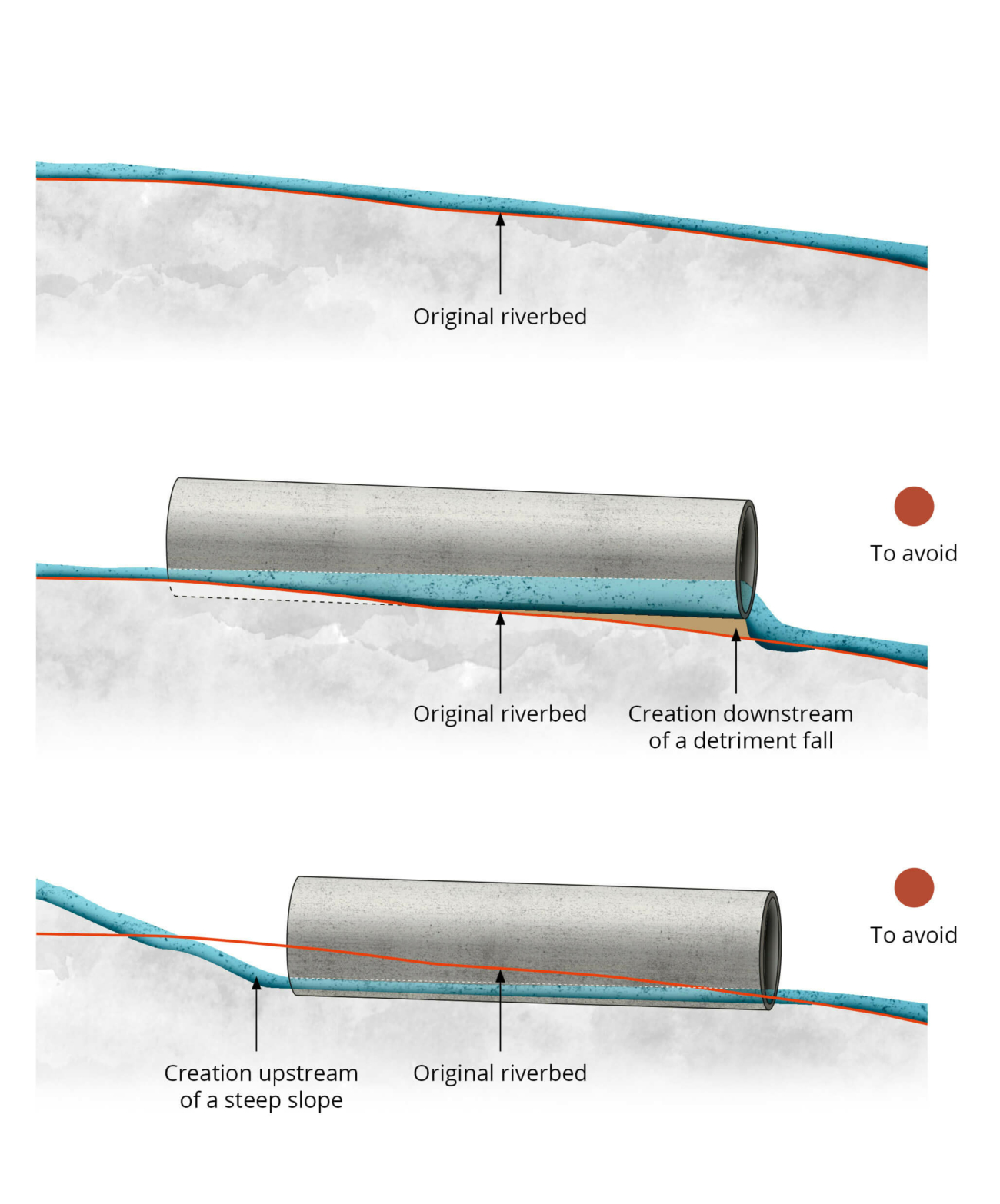
- If the foundation of the passage is positioned at a different slope to the original riverbed, the structure creates breaks in the natural slope. This results in water chutes downstream or steep slopes upstream which reduce depth and increase water velocity. Both problems create difficulties for fish movement (Figure 5.5.44).
- Structural problems inside the passage, such as steps caused by inappropriate joints between parts of the structure, must be avoided as they can reduce the flow and make fish movement difficult.
- Inadequate water depth within the passage may pose problems for a variety of species. Different species have different demands at different stages of their life cycle and periods of the year, e.g. adult salmon require a water depth of at least 20 cm, while trout require a depth of 5 to 10 cm. A smooth base combined with an unsuitable slope may result in water depths making it difficult or even impossible for fish to swim through the structure during drier periods. Appropriate width of the structure, according to the watercourse minor bed is necessary for the required depth to be achieved. Too wide and the water may become too shallow to allow fish to move through it.
- Excessive water velocity within the passage hinders movement of fish. An insufficient width creates excessive water speed within the passage and creates a current in excess of the swimming capabilities of the fish. A smooth base substrate and too high a current through the passage leave no resting zone for fish trying to use it.
- Hydraulic simulation (see section on design) is necessary to ensure the correct dimensions when designing culverts modified to allow fish passage. Flow velocities must be analysed under conditions of low and higher water in line with the expected operating range of the structure. The water velocity can also be reduced by installing thresholds, deflectors or macro-roughness treatments which raise the height of water and diversify its flow. In downstream and steep culverts, the riffle has to be high enough that the water line in the entire culvert is at the same level. This solution requires appropriate maintenance as sediments and debris will be deposited in the pools.
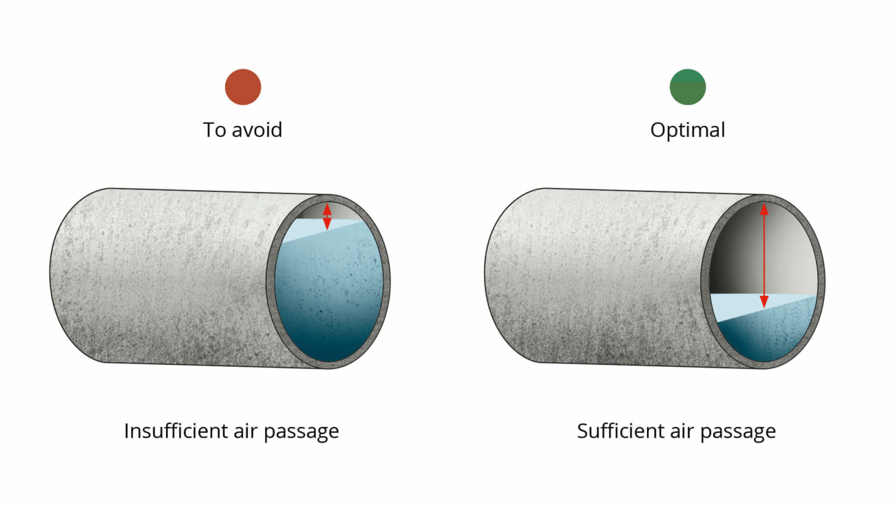
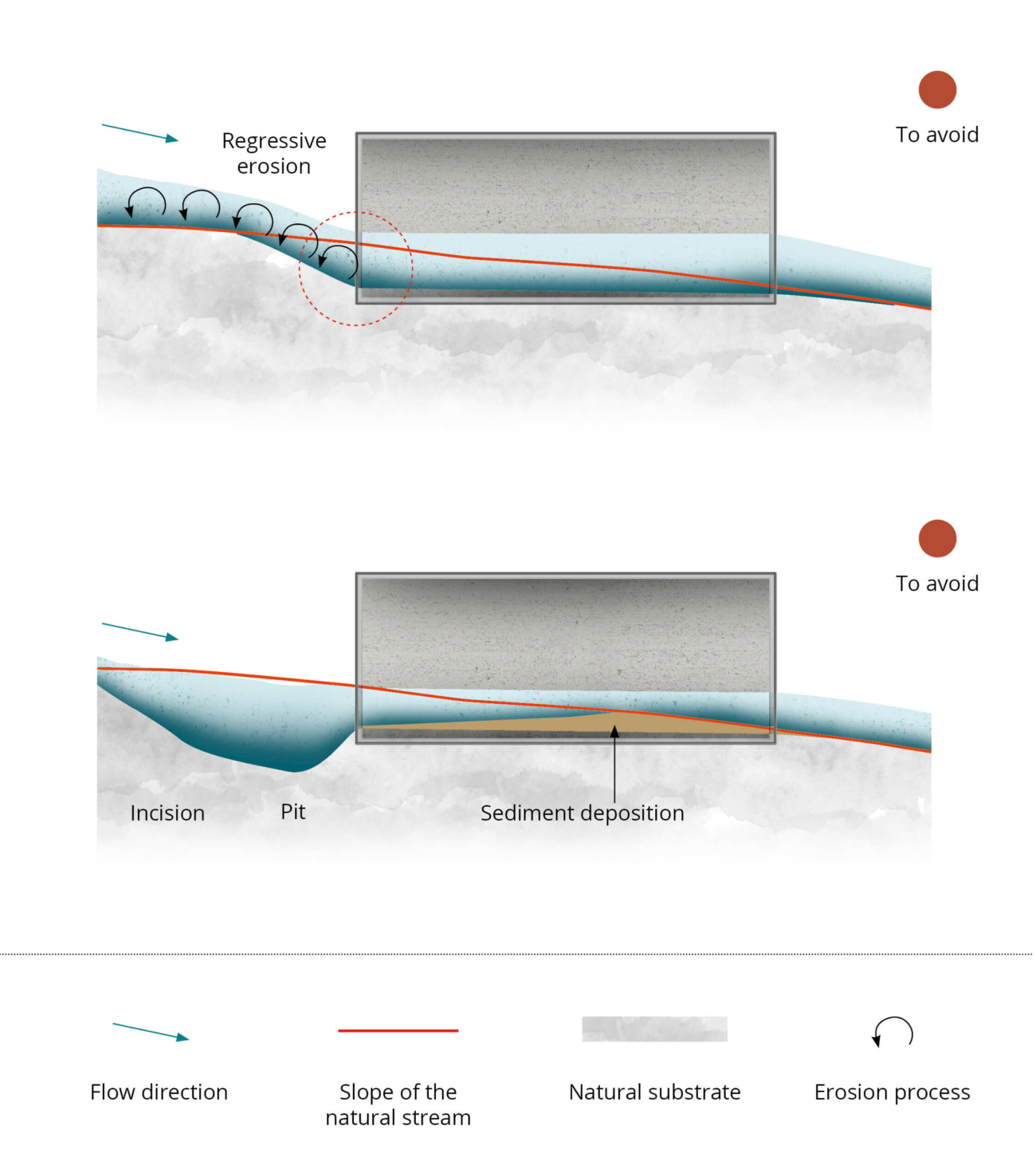
- Debris accumulation can create barriers to fish within the passage. This happens when structures are undersized in relation to the width of the watercourse, when there is a strong narrowing of the passage section, or if the air draft between the water line and the entrance of the passage is insufficient (Figure 5.5.45). Debris and bed material should be managed by collecting it upstream or allowing it to pass unhindered through the passage. Debris accumulation can also create a hydraulic swirl upstream which affects fish habitats and may render the passage non-functional (Figure 5.5.46).
Choice of the structure type
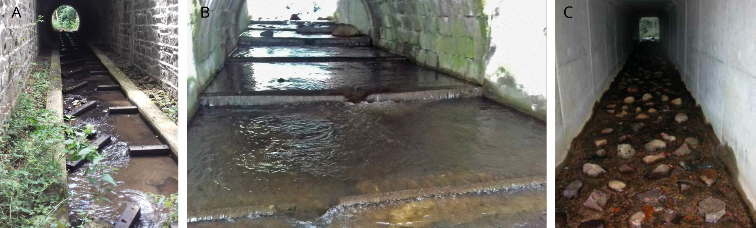
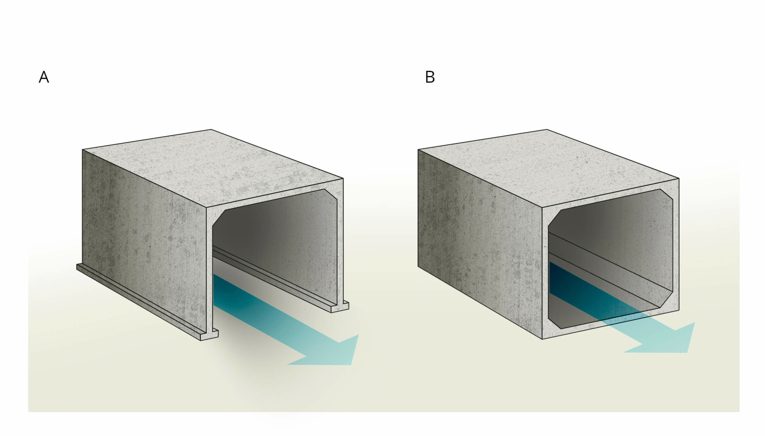
For hydraulic structures, passages open to the ground (Figure 5.5.47A) without concrete on the base, must be installed unless technical issues make this impossible. The choice of structure depends on:
- the physical and biological components of the watercourse to be crossed, and in particular its ecological challenges.
- other functions and uses that the passage will restore (flood expansion zone, pedestrians, animals, etc.).
- cost considerations.
When the surroundings of infrastructure present unavoidable issues relating to watercourses and/or the local ecosystems, solutions to mitigate the impact on these is essential and it is strongly advised:
- to find an alternative to the pre-defined infrastructure route.
- where re-routing is not an option, installing open structures such as viaducts provides the greatest water connectivity and maintains the natural functions of the watercourse by preserving the minor bed, riverbanks, even in some cases the riparian forest and the watershed associated with the watercourse. Fish movement is maintained, avoiding the installation of heavy and expensive devices for bank protection and energy dissipation.
Verifying the correct conditions enabling fish to cross the structure
Correctly sizing a structure which allows fish to cross entails a comparison between the swimming capacities of the fish and characteristics of the water flow within the structure, including water height, the presence of drops, water speed and distance to cross. The hydraulic design process is based on the maximum water current speed that the target fish species can withstand, depending on the length to be crossed. The longer the distance, the lower the maximum permissible speed.
Not every animal using a water passage to cross the infrastructure will swim through it. Eels for example may also crawl, however in this document, swimming is the main means of movement dealt with.
- The swimming ability of target species is a reference to consider in the design of the structure. The ‘cruising speed’, which corresponds to the speed an individual fish can maintain continuously for more than 3 hours, is used as the design reference because it is the speed that can be maintained over long distances.
- The speed of the current and water level in the structure determines the potential for a target species to cross the structure. Hydraulic simulation must be undertaken in order to check compliance with depth and flow speed required for the less capable target species. Issues to be considered are:
- maximum passable distance for a target species, depending on the flow speed in the structure and is strongly associated with its shape, roughness and slope. Flow speed should be equal or inferior to the ‘cruising swimming speed’ of target species, for flows between ‘low water’ and up to 2.5 times the debit inter-annual average.
- minimum water depth required by target species, which is in the range of 5 cm for small species (sculpins, studs, minnows, groupers) to over 20 cm for adult Atlantic salmon.
Positioning of the structures
- Open structures: bridges and viaducts (Figure 5.5.47A). Foundations must be laid as far back as possible from the minor bed, the banks and the riparian forest in order to guarantee the stability of these environments and to restore ecological continuity. Well dimensioned, these works should not require the installation of any additional equipment. These design features should be prioritised in new infrastructure projects.
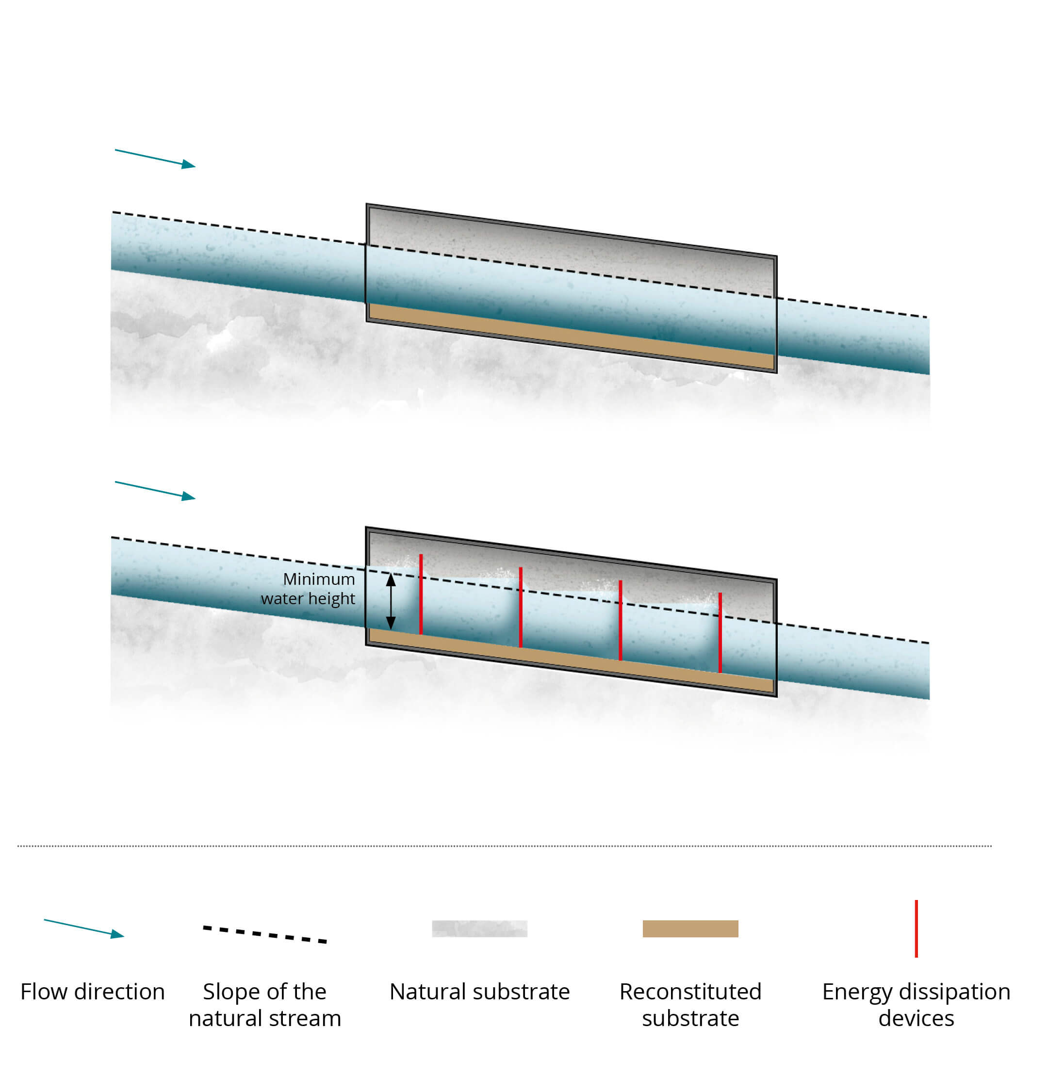
- Closed structures: culverts (Figure 5.5.47B). These must be positioned similar to the initial precise longitudinal profile of the watercourse which must be determined by a precise topographic survey. The objective is to reconstitute a natural background while avoiding the presence of steps or any other obstacle causing different water levels upstream and downstream from the structure and taking care not to create breaks that would give rise to erosion. Once slope angles are determined, the leading edge of the foundation should be installed at least 30 cm below the natural bed of the stream (Figure 5.5.48). Burying the foundation also makes it possible to correct small errors in the positioning of the structure during installation and recreate a favourable rough bottom surface.
It may arise that an existing structure must be modified to allow fish passage, but the conditions already listed cannot be achieved due to characteristics of the watercourse (hydrological regime, width or slope), the structure (dimensions or positioning) or the target species present in the catchment area. In this instance, devices for energy dissipation should be installed at the basis of the structure which would allow the substrate to be maintained and/or raise the water line (Figure 5.5.48).
Openness Index
Studies have shown that the ability of fish to cross hydraulic structures is improved by an optimal Openness Index (ratio between section and length). The openness should increase as a function of the length of the cover (Table 5.4).
If length reaches or exceeds 60 m, it is necessary to consider modifying the structure (in the case of several consecutive structures, the cumulative length should be considered).
Reducing the length of structures, by constructing wing walls or vertical embankment retaining walls, are measures to be considered.
Table 5.4 – Modulation of the section / length ratio according to the length of cover (Source: Setra, 1993; River and stream continuity partnership, 2011).
| Cover length (single or cumulative) | Section / length ratio |
| L < 30 m | 0.25 |
| 30 m ≤ L ≤ 60 m | 0.50 |
| L > 60 m | 0.75 (or use another type of structure: viaduct, bridge) |
Substrate
A bed of substrate that mimics the natural watercourse as closely as possible must be laid on the base of the structure to a depth of at least 30 cm. The size of particles used in this substrate is very important to maintain the circulation of fish and the ecological capacity of the watercourse. The substrate must avoid any infiltration which would reduce the flow or even cause the structure to dry up.
Once the grain size has been decided, it is important to ensure that the substrate cannot be stripped by being lifted and carried away, especially when the flow rate is at its maximum speed in the structure. If this is a risk, a substrate stabilization threshold or deflectors will prevent periodic stripping (Figure 5.5.49).
Energy dissipation devices
When the conditions that allow fish movement cannot be reached or maintained it will be necessary to add energy dissipation devices and / or water line enhancement.
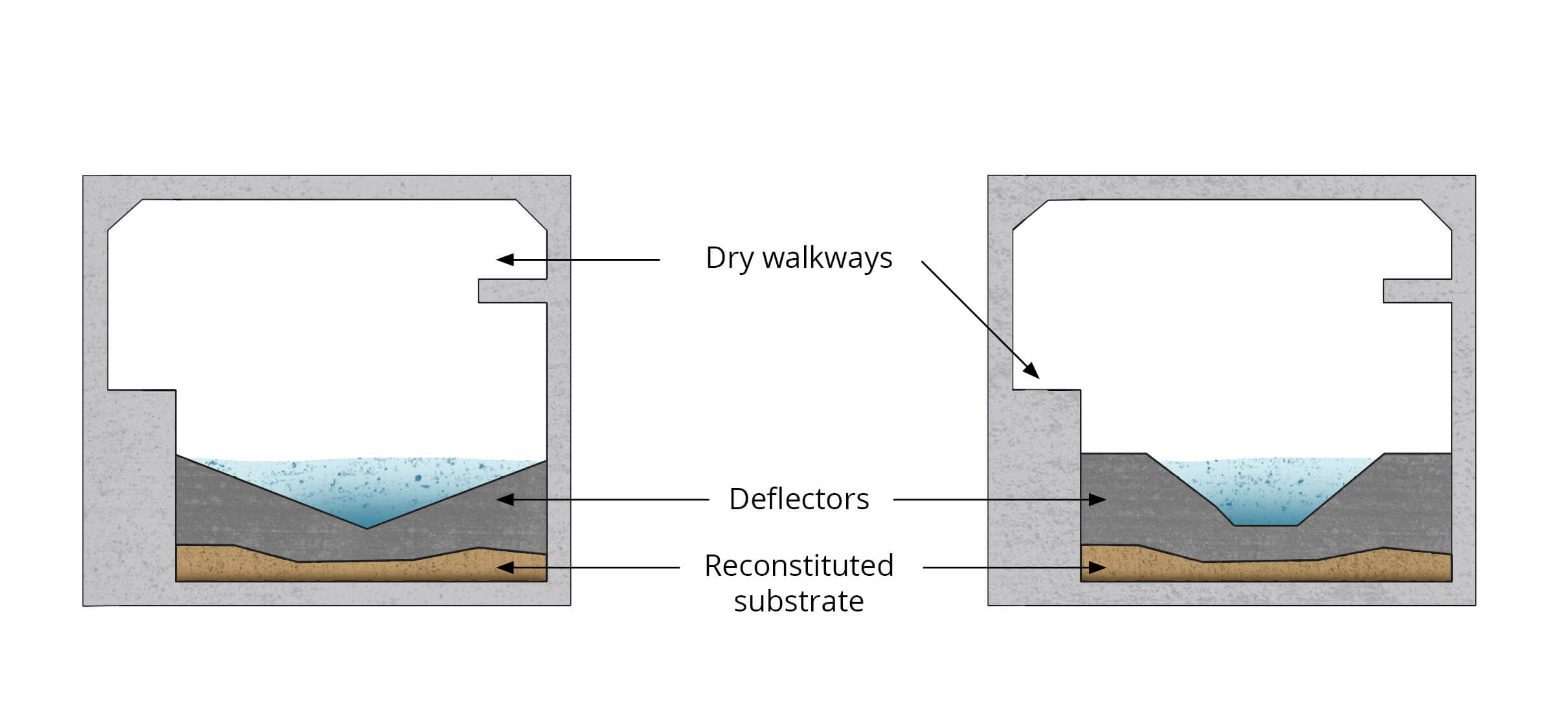
- Thresholds, deflectors (baffles) or macro-roughness such as blocks bonded to the bottom of the structure, positioned transversely or staggered, will decrease the speed of the current, stabilize the substrate and / or enhance the water line, which ensures conditions compatible with fish swimming abilities:
- Thresholds (Figure 5.5.50A) are triangular crest sills which have the advantage of creating heterogeneous flow conditions, the fish being able to choose the passage zone which suits them best according to the flow conditions.
- Deflectors (baffles; Figure 5.5.50B) are more difficult to install and more expensive given their inclination, their reduced spacing and, consequently, their number.
- Macro roughness substrate (Figure 5.5.50C): the reconstitution of a “natural” bottom makes it possible to restore a roughness to the raft. In addition, large diameter blocks, made of concrete or natural materials, can be positioned regularly and/or staggered. The latter create a heterogeneous flow within which the fish can find their preferred path.
The nature, quantity and spacing of these deflectors must be determined on the basis of a specific hydraulic study and according to the requirements of target fish species. Installing thresholds combined with macro-roughness substrate may also be considered.